Making a renovated 70’s house breathe
Introduction
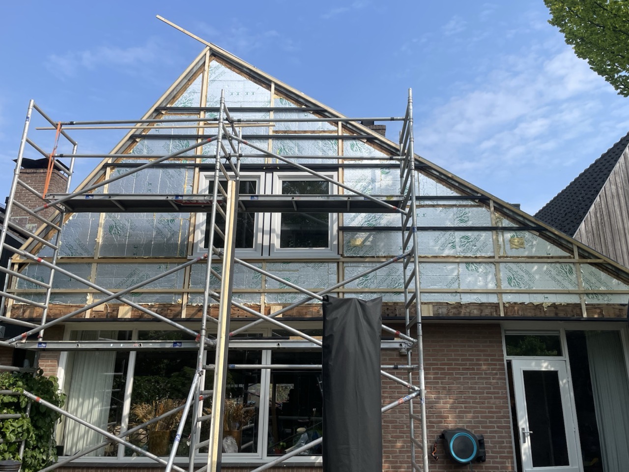 We own a house from 1978, and last year we hired a contractor to renovate the upper-floor exterior of the house at the front and back side, including new windows. We also installed screens which completely block all light (and air, we found out later). Now we’re no longer leaking expensive heat in the winter :P
This did lead to a new challenge around air quality upstairs, especially during the night and in winter. With the new triple-glass windows and nice screens we would like to keep them closed to take maximum benefit from them. But with no mechanical ventilation system in place, the CO₂ levels were at alarming levels. Even with the windows open and the screens closed, that hardly led to natural airflow anymore.
Requirements for a ventilation system
I wanted to have control over it myself, as I’d like to tweak when it runs and how noticeable it is. Just having a fixed setting or curve wouldn’t be enough. Also, I wanted the control to be stepless, instead of the traditional 3-step selectors. I’d get pretty frustrated hearing the thing oscillate between step 1 and 2 every few minutes during the night, for example.
Steps
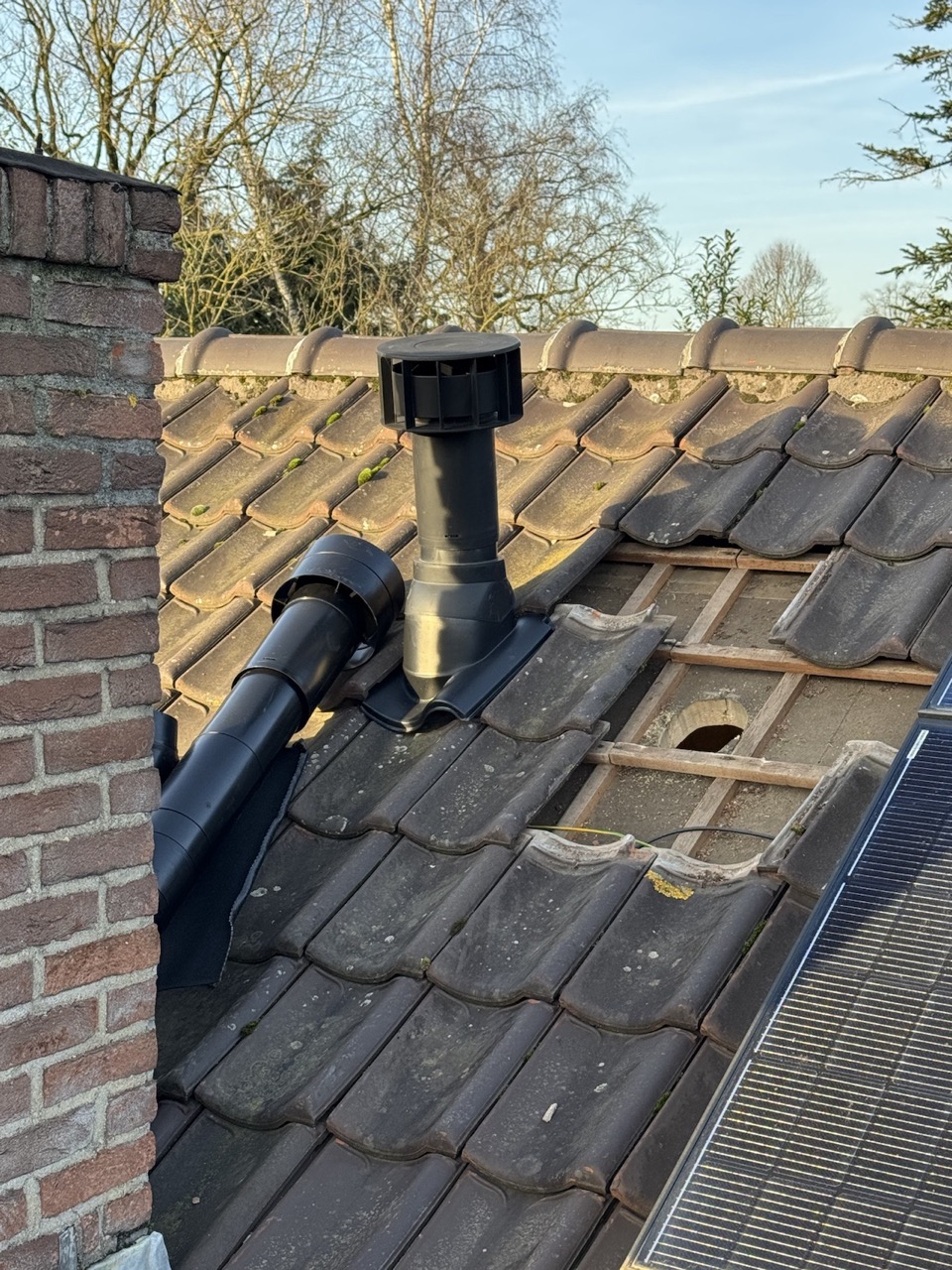 To make the work manageable, I chopped it up into smaller parts.
- Figure out which system I’d need, what roofing and ductwork would be required, and where the ventilation valves in each room would be.
- Select a ventilation box (brand and type)
- Do the roofing work
- Set up the ventilation box, including control
- Do the ductwork to all the rooms
In hindsight I spent way too much time on step 1, because I wanted to know everything ahead of time and have my measurements correct. I probably would have been better off just ordering an extra tube or bend and being done with it.
Ventilation systems
Picking which system and product I’d want was an interesting adventure, as I learned a lot of new things about ventilation systems in general. Do I need only extraction? Or also supply ventilation? What pipe dimensions, what flow rates do I need? Do I need one-way valves, and where? My wife found noise dampeners and really wanted them, but how do they work and where do you place them?
Let’s start with an overview of which systems there are.
- A: Natural ventilation. In other words: just open a window.
- B: Mechanical supply ventilation. I’ve never seen anybody install this in houses.
- C: Mechanical extraction ventilation. This is most often used in older buildings, especially in the bathroom and kitchen.
- D: Combination of B and C. Often combined with a heat-recovery system.
On top of that, system D can even be combined with active heating or cooling of the supplied air. Now we’re getting into typical American HVAC systems (Heat, Ventilation and Air-Conditioning). Usually in Dutch houses there is a central heating system already in the form of radiators or underfloor heating. So a heat-recovery system is common in newer houses, while active heating/cooling inside the ventilation system isn’t.
I picked extraction (type C), as the price compared to a full D system and the required ductwork is far less. Also, the provided air circulation should be sufficient by using the ventilation vent already in the window(s) as supply.
Why not type B? I don’t know. I don’t see it being installed that often. It’s often used in industrial settings, but not in houses. There aren’t many residential products for type B to be found. I also think it makes more sense to extract air than to inject new air? Probably less turbulence and more predictable airflow.
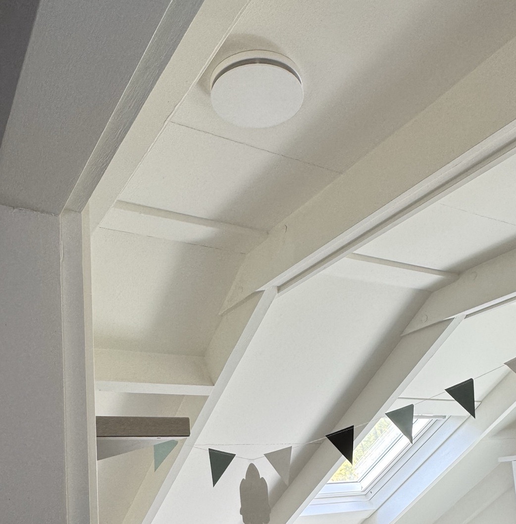 I’ve placed the ventilation valves such that the fresh air from the window vents crosses the CO₂-producion facility in each room. Except for our bedroom. I wasn’t able to place it optimally there, but as we see in the results later, that didn’t matter that much fortunately.
With extraction only, and having a single window ventilation vent open in each room, I would be able to control both supply and extraction, as there is no air draft in a room when there is only one window ventilation vent open. That means I would only move the air when it’s actually needed, at the rate that’s needed, so that I keep most of the heat in. For me, this balanced the installation effort, heat loss of the ventilation system and air quality.
The ductwork
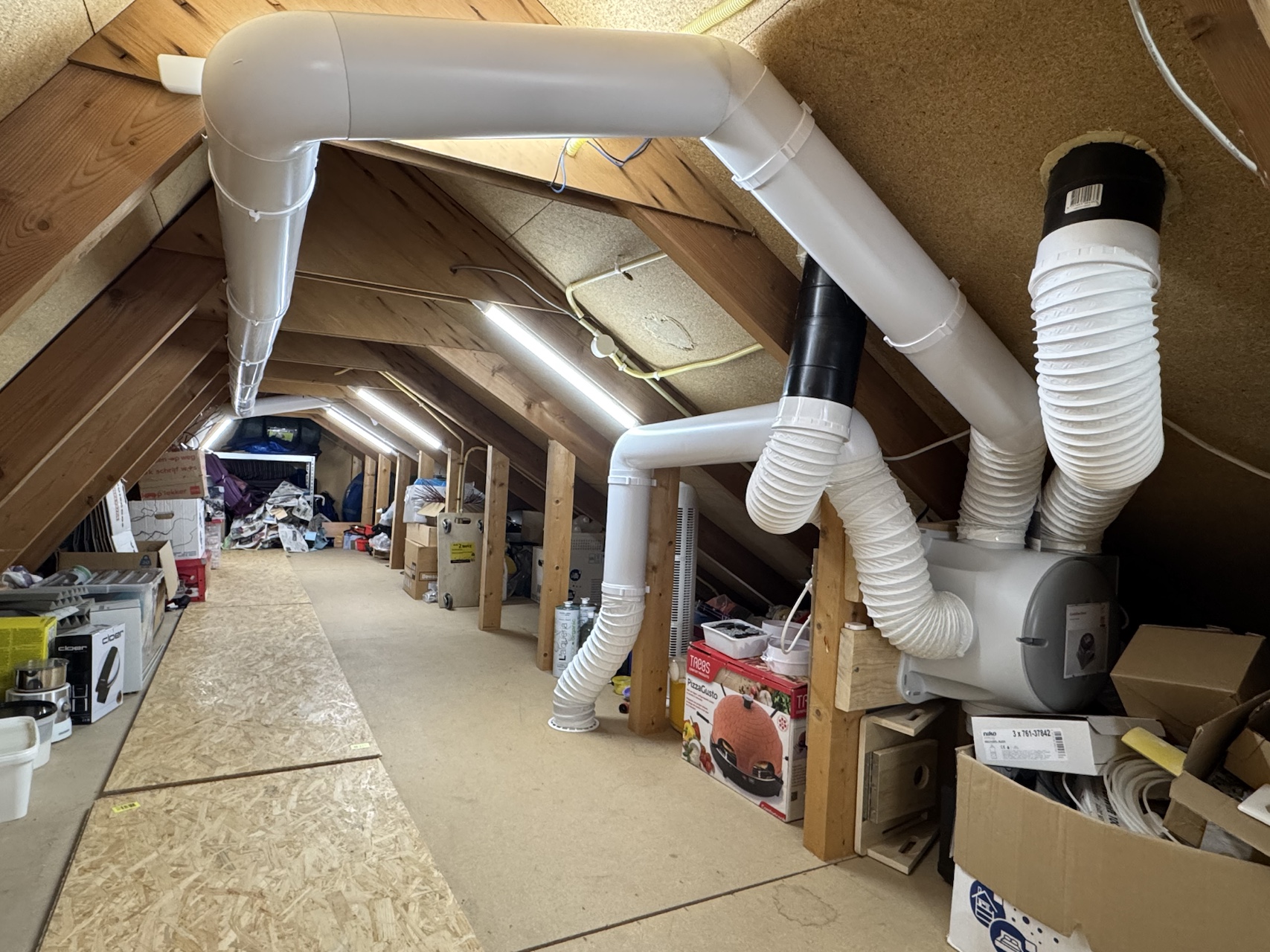 Omg, the ductwork… It’s easier than it looks, but it takes more time than you’d think. Like with electrical work, the fun part only comes when you’ve got the infrastructure there… I’ve chosen slightly larger diameter pipes than I needed, and ended up with the default smooth 125 mm diameter pipes. Why?
- The smoother the pipes, the less noise, so keep flexible-pipe sections as short as possible and only when you need them.
- The bigger the pipe, the slower the air can move for the same volume moved, and thus less noise.
 Placing noise dampeners (which you place near the valves in the rooms) is also a good idea if you want to reduce cross-talk between rooms (when those rooms use the same ductwork back to the ventilation box) or when you want to reduce motor noise. Using PVC ducts instead of metal ones also helps. Popping out the pre-cut sections can also be used to roughly distribute airflow between rooms. You later fine-tune the actual airflow with the valves in the room.
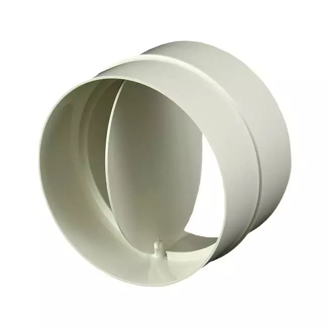 Normally you are advised to never turn off a ventilation system. This is mostly because the building was designed with the system in mind. Turning it off makes the air go stale because there isn’t enough natural ventilation anymore, because of how well insulated and closed off houses are now. But, I do intend to turn mine off. I believe I can do that because I’m monitoring conditions, and it turns on when needed. When you do however turn it off, you still want to prevent outside air from reaching into the rooms, because we also have a chimney close next to the exhaust, which we actually use in the winter. This one-way valve does exactly that. I’ve placed one between the ventilation box and the house exhaust, which is sufficient I think.
The box itself
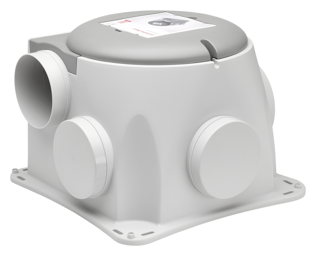 I’ve chosen the “Zehner ComfoFan Silent Limited - RA” specifically, because:
- I didn’t need a remote control or traditional 3-selector wall control, and thus didn’t need a Perilex connector (RA vs P version). This just connects to a normal electrical outlet.
- I didn’t need any sensors included in it, because I want to control it manually. This one only had an embedded humidity sensor, which you can effectively disable by setting its curve to 0.
- I wanted a system as silent as possible, so chose the “Limited” version. It is specced lower than the non-limited versions, but you only need that for wet rooms like the shower. I didn’t intend to use it for that.
- I wanted a system which I can control steplessly via a preferred open protocol. None of that WiFi or cloud-connected crap where the app breaks after a few years. This was the only type C system I could find that allowed control via a 0-10V line you’d normally use for lighting.
Preferably, I’d like to power down the complete system when no ventilation is needed. Most ventilation boxes go into pairing mode for wireless remotes when you reconnect them to mains power. I didn’t want that, because it could accidentally cause a neighbor’s remote to be paired to my ventilation box. From what I could find, this specific box doesn’t support remotes, so no pairing mode to worry about :)
CO₂ sensors
 Not all CO₂ sensors are created equal. NDIR-based sensors are considered very accurate, but are also usually expensive. In the living room, I have an AirGradient which uses a SenseAir S8 sensor. I like it a lot and it provides a lot of measurements! But it’s way too expensive to put one in each bedroom. So, I’ve opted for the ESPHome-based CO₂ sensor from Athom Tech, which is a VERY affordable, good sensor mounted on a PCB in a plastic case. It’s as bare-bones as you can get while still calling it a product :). I like it!
Later, the IKEA ALPSTUGA finally became available, and I got a chance to test it. The CO₂ readings from that are decent for getting a ballpark value, but for me, they’re not accurate enough to run the ventilation on. I ended up using them in the caravan, because it is still a very nice sensor with plenty of other features, and at an even more awesome low price tag!
Controlling it
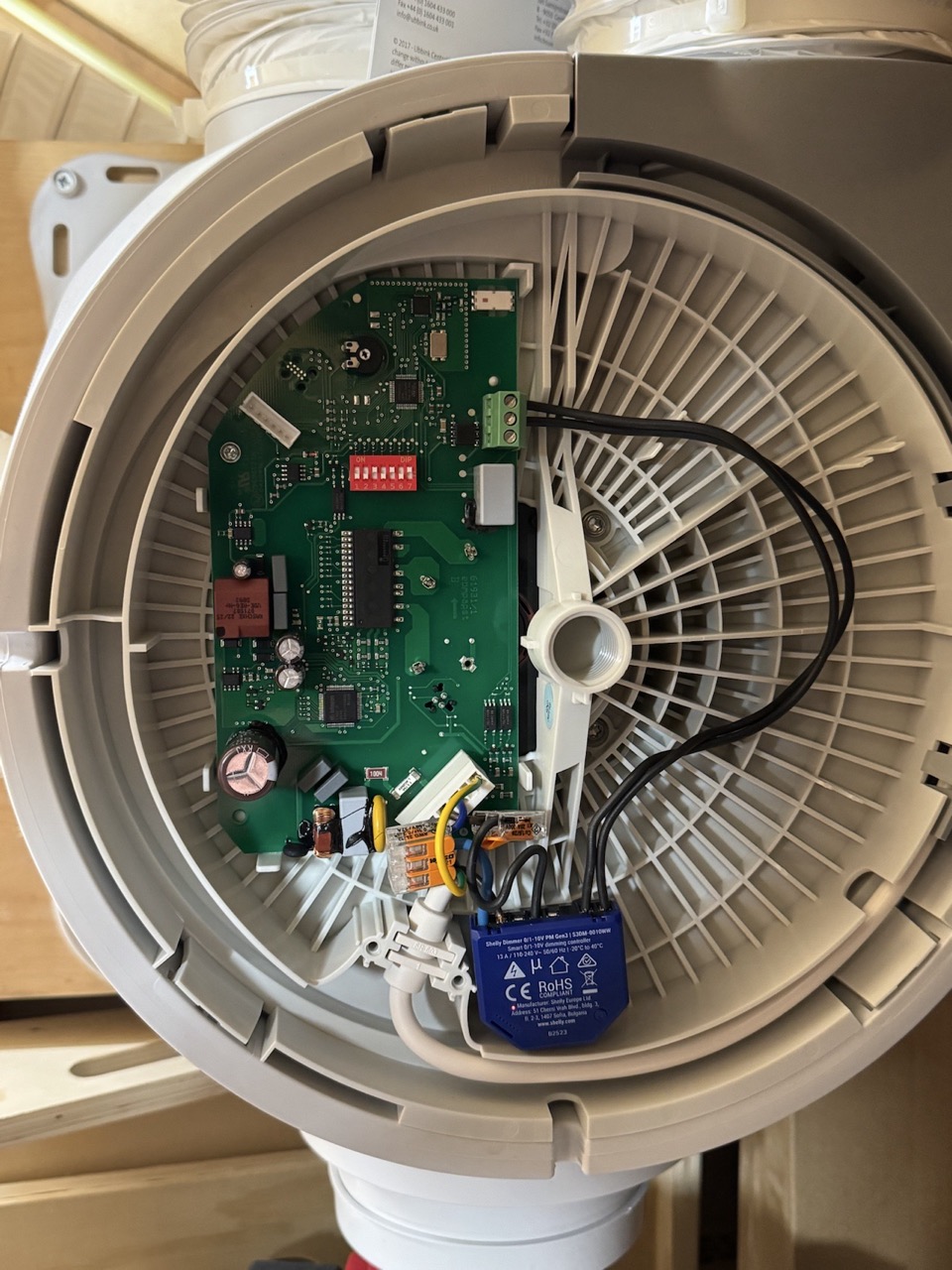 The box supports control via a 0-10V line, which is often used in office lighting. It works by sending an analog signal in the form of a voltage between 0-10V DC across two wires, by which you can tell the fan (stepless!) how fast to run. The 0-10V lines don’t carry any load. The light fixture (or ventilation box in this case) has continuous mains power, and controls the intensity itself according to the signal received.
There are plenty of 0-10V dimmers to be found when you start looking for them. I’ve chosen one from Shelly, because it was priced right, they build quality hardware, and most importantly: it is locally controlled natively from Home Assistant. You don’t even have to use their app for the initial setup if you don’t want. Another nice thing is that if you tell it to go to 0%, it actually disconnects the power from the ventilation box. And as a bonus, it includes power measuring! All of that in a single module. I couldn’t have built a nicer system with ESPHome myself.
With plenty of room left in the ventilation box, you can easily fit a Shelly inside it.
Determining demand
I already had CO₂ sensors in every room. So, at any given time, pick the highest value of any of those sensors and based on a curve, determine the speed at which the fan must turn.
Yes, this can in theory lead to oscillating behaviour, but even tuning this pretty aggressively (off at 600 ppm and 100% at 1200 ppm, and it has quite some air volume it can move at 100%), and no averaging of CO₂ values over time yet, it didn’t lead to oscillating behaviour yet. Even though it responds pretty quickly when you’re with multiple people in a single room. I think this is because I placed the CO₂ sensors out of the airflow in each room. It ends up with a natural averaging of the value in the room.
Code
Finally! Some code :)
The Shelly is represented in Home Assistant as a light, so let’s first make it represent a fan properly.
template:
  - fan:
    - name: "Boven ventilatie"
      default_entity_id: fan.boven_ventilatie
      unique_id: boven_ventilatie
      availability: "{{ not states('light.ventilatie_boven') in ['unavailable', 'unknown'] }}"
      state: "{{ is_state('light.ventilatie_boven', 'on') }}"
      percentage: >-
        {% if is_state('light.ventilatie_boven', 'on') %}
          {% set pct = (state_attr('light.ventilatie_boven', 'brightness')|float(0) / 255 * 100)|round(0) %}
          {{ [ [pct, 1] | max, 100 ] | min }}
        {% else %}
          0
        {% endif %}
      speed_count: 100
      turn_off:
        - action: light.turn_off
          target: { entity_id: light.ventilatie_boven }
      turn_on:
        - action: light.turn_on
          target: { entity_id: light.ventilatie_boven }
      set_percentage:
        - action: light.turn_on
          target: { entity_id: light.ventilatie_boven }
          data: { brightness_pct: "{{ percentage|int }}" }
Gather the maximum CO₂ value from all CO₂ sensors upstairs by utilising Home Assistant’s floors and rooms feature!
template:
  - sensor:
    - default_entity_id: sensor.boven_ventilatie_max_co2
      unique_id: boven_ventilatie_max_co2
      name: boven_ventilatie_max_co2
      state_class: measurement
      unit_of_measurement: "ppm"
      device_class: carbon_dioxide
      availability: >-
        {{
          floor_entities("Boven")
          | select("is_state_attr", "device_class", "carbon_dioxide")
          | map("states")
          | reject("in", ["unknown", "unavailable", ""])
          | list
          | count
          | int > 0
        }}
      state: >-
        {{
          floor_entities("Boven")
          | select("is_state_attr", "device_class", "carbon_dioxide")
          | map("states")
          | reject("in", ["unknown", "unavailable", ""])
          | map("float")
          | max
        }}
Then, let’s build a sensor which determines the desired fan speed from the curve.
# Declare inputs to set the curve from the UI
input_number:
  boven_ventilatie_max_fan_speed:
    unit_of_measurement: "%"
    icon: mdi:fan
    min: 0
    max: 100
    step: 5
  boven_ventilatie_min_co2:
    unit_of_measurement: "ppm"
    icon: mdi:molecule-co2
    min: 0
    max: 800
    step: 100
  boven_ventilatie_max_co2:
    unit_of_measurement: "ppm"
    icon: mdi:molecule-co2
    min: 1100
    max: 2000
    step: 100

template:
  - sensor:
    - default_entity_id: sensor.boven_ventilatie_desired_fan_speed
      unique_id: boven_ventilatie_desired_fan_speed
      name: boven_ventilatie_desired_fan_speed
      state_class: measurement
      unit_of_measurement: "%"
      availability: "{{ states('sensor.boven_ventilatie_max_co2')|is_number }}"
      state: >-
        {% set min_co2 = states('input_number.boven_ventilatie_min_co2')|float(0) %}
        {% set max_co2 = states('input_number.boven_ventilatie_max_co2')|float(0) %}
        {% set max_speed = states('input_number.boven_ventilatie_max_fan_speed')|float(0) %}
        {% set co2 = states('sensor.boven_ventilatie_max_co2')|float(0) %}
        {% set pct = ((co2 - min_co2) / (max_co2 - min_co2) * 100) %}
        {{ [ [pct, 0] | max, max_speed ] | min | round(0) }}
And then the automation to make it apply to the fan.
automation:
  - alias: boven_ventilatie_update_fan_speed
    id: boven_ventilatie_update_fan_speed
    initial_state: true
    triggers:
      - trigger: state
        entity_id: sensor.boven_ventilatie_desired_fan_speed
        not_to: [unknown, unavailable]
    variables:
      desired_fan_speed: "{{ states('sensor.boven_ventilatie_desired_fan_speed')|float(0) }}"
    actions:
      - action: fan.set_percentage
        target: { entity_id: fan.boven_ventilatie }
        data: { percentage: "{{ desired_fan_speed }}" }
Tuning
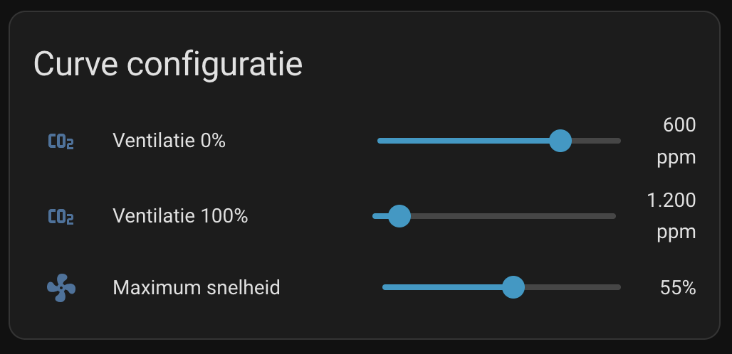 Once I had the system running and somewhat functioning, it was time to fine-tune it. I don’t have a ventilation box per room, so I control 4 rooms with a single fan speed. One bedroom would have way lower CO₂ values than the other, so I closed or opened the valves in each room as required, until the values are roughly equal.
Also, running the fan at 100% would be very noticeable, but below a certain value, no longer. So I’ve set that value as the maximum it’s allowed to run. I am considering applying that maximum only during the night, but I also haven’t had a reason during the day yet to have it run faster than that.
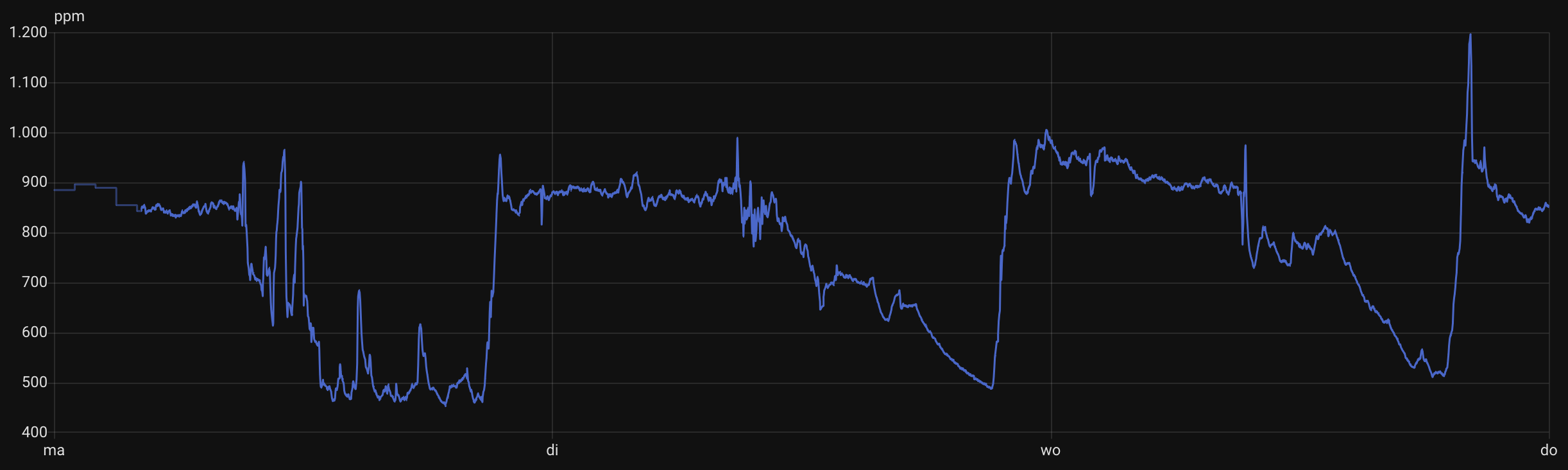 Then, the aggressiveness of the curve. Setting the lower value of when to turn on too low leaves it running for most of the day, while that isn’t needed. Setting the upper bound too high causes it to never properly get the CO₂ values down. Setting that curve too aggressive can lead to oscillating behaviour.
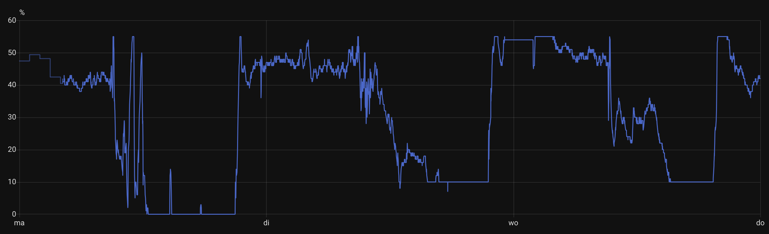 As you can see on the right, the fan speed graph is pretty aggressive, but I haven’t noticed it yet, and I do like how fast it responds to high values. So no need to smooth that out yet by averaging it for example.
I also let the system run at 10% when the air conditioning unit in the hallway upstairs runs. It helps with the distribution of that air and slowly gets rid of hot pockets of air in the top of the rooms.
Effects
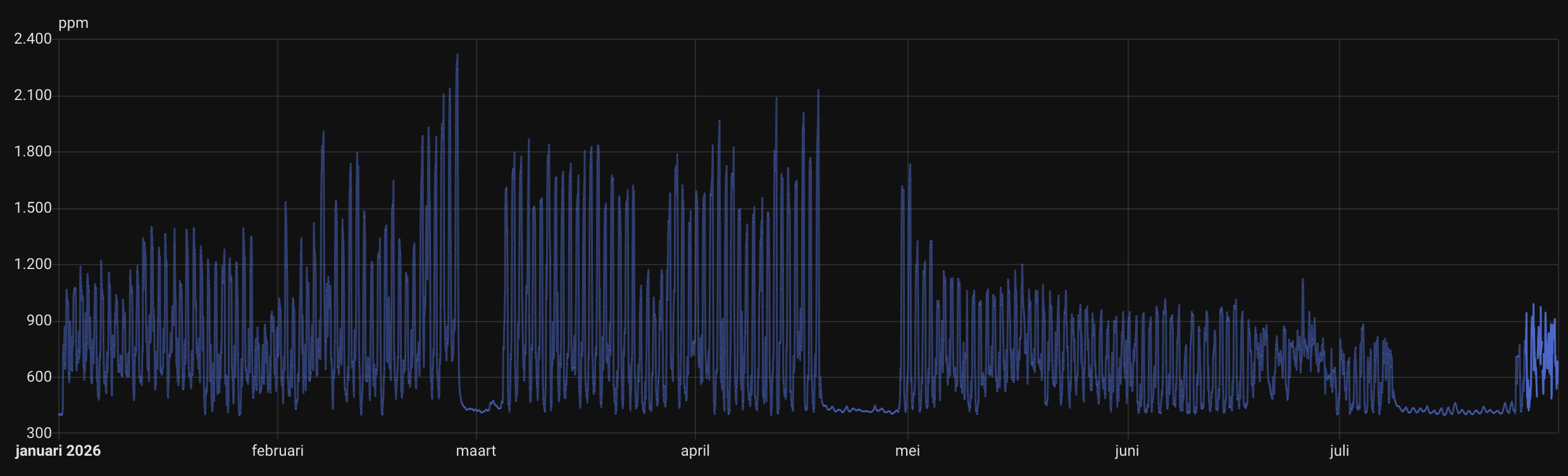
The graph here shows before and after activating the system beginning of May. It stays well below 1000 ppm and often below 900 ppm, which is really nice. Also, opening or closing the windows at night with the screens closed barely has any effect on the CO₂ levels.
Another cool effect of this was that it even helps with the CO₂ downstairs. In the living room we don’t have any ventilation and rely on natural airflow (System A if you’d like to call it that :P). Having visitors over or a birthday party often gets the CO₂ to unhealthy levels, and a display telling us about that ends up with us opening doors or windows.
We also have an air conditioning in the hallway upstairs, and we leave the hallway door downstairs open on really hot days. Recently, these combined: It was a very hot day at 39 degrees Celsius outside. The airco caused air circulation between downstairs and upstairs. This caused plenty of the CO₂ to travel upstairs and exit the house, while cool air entered the living room. The effect was way lower CO₂ levels in the living room than usual with this amount of people.
Closing
I’m very happy with the system, and after tuning it, I haven’t touched it once. This is a great addition to the house and also very much liked by the rest of the family.
Leave a comment