Putting ESPHome on a Button+
Introduction
The Button+ is an awesome modular wall panel (go check out their website, it looks awesome!). A friend of mine and I bought one each, even though I don’t have a use case for it yet. But you can be damn sure it’s going somewhere on a wall here.
It is a genuinely cool bit of hardware and we had a lot of fun fiddling with it. But I didn’t like the stock firmware much, and there wasn’t a usable ESPHome configuration for it.
So with the help of Claude Code, I (ahem, Claude mostly) built a config and open-sourced it! Heck, even half of this blog post is written by Claude and half by me.
Regardless, this post is about the very cool journey to do that.
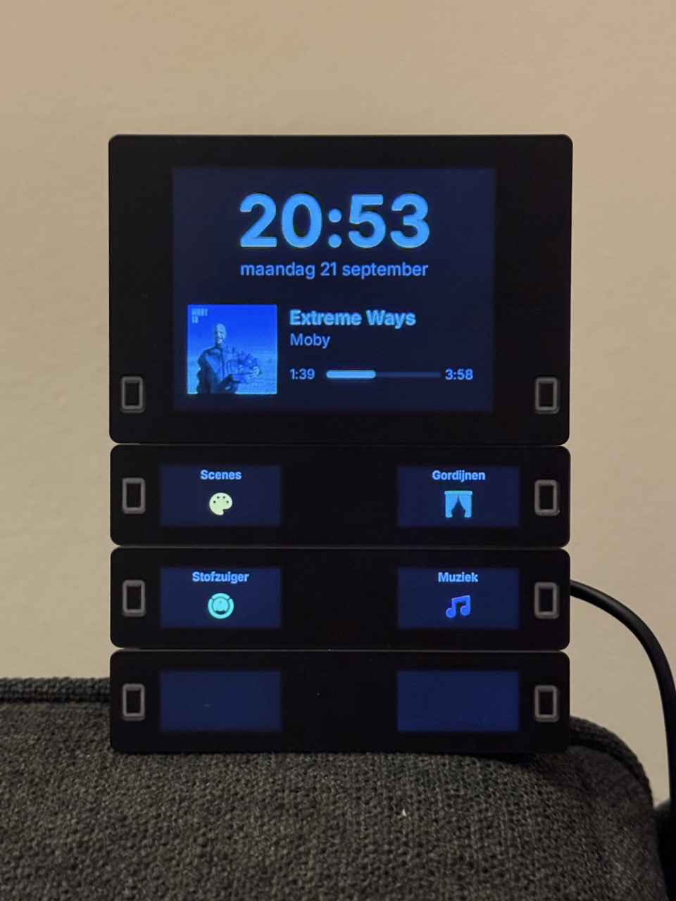
The hardware
Physically it is lovely. The modules click together, the buttons feel good, and a stack of small screens next to physical buttons offers possibilities for cool interactions. It makes it flexible and great fun to add functionality to.
There are some things to note:
- The displays are dim. Not unusable, but noticeably dim. In a room with a lot of daylight I suspect they would be hard to read. In the evening they are perfect.
- There are no hardware interrupts for the buttons. Every button hangs off an I²C port expander, so the only way to notice a press is to poll the expanders from the main loop. That sounds like a detail, but it turns out to be the constraint that shapes everything else. Anything that blocks the loop eats button presses. More on that below.
- The 8MB PSRAM is very welcome. The V1 base module had to make do with the 512kB of RAM in the ESP32 itself, and seven framebuffers is about 300kB of that. This is what makes a proper graphics stack possible on the V2 at all.
The vendor firmware
The firmware is still quite new and somewhat buggy. Not unusable, but it does get in the way sometimes, like the overlay dialog leaving fragments behind on the screen, or it often needing a second reboot to connect it to the network properly. From my experience with ESPHome, I knew it could do better than that. With upwards of two hundred home automation devices in the house, I need something that comes back up by itself, for example when the power goes out and returns. Also, I’d rather get it running in an open system which I already knew, than to learn or adopt a vendor-specific way of controlling it.
My biggest issue with the firmware though was the limited support for graphics on the display. You have this really awesome big display, but all you could get it to display was text, some lines and a weather icon. I like the simplicity, but I think this is a bit too limited.
Also, personally, I like the integration with ESPHome and Home Assistant better than going through MQTT. MQTT isn’t bad, just that ESPHome is more user-friendly for me to handle. And I get why they chose MQTT: it makes the device usable beyond Home Assistant.
Going ESPHome
Most of the devices in my house already run ESPHome, so that was the obvious direction. The question was whether the panel could be driven from it at all.
It could. dixi83/ESPhome_ButtonPlus already had a working ESPHome config for the V1 hardware. That project does not run on a V2, because V2 moved the display bus and swapped the two I²C buses around to make room for the PSRAM. It did prove the concept though, and it documented how the modules are wired up. That was enough to know it was doable.
So, with that as a starting point, the published V2 schematics, the ESPHome documentation and Claude Code, I started building.
AI entered the chat
So, there are a lot of things to figure out.
- How is the V1 hardware different from V2
- Quite some trial-and-error iterations to get the hardware right
- Changing approaches to handling button events and pagination as we go
- Making sure the implementation is responsive and performant, not just working.
Apparently with all of these, AI can be a great help, as long as you give it a feedback loop: It needs to be able to verify its work. The following helped achieve that:
-
Giving it the ability to flash the device. It could compile, flash over OTA, add temporary logging, read the logs back, and iterate on its own. Several times it tried out two or three approaches on its own, flashed each one, measured, and decided based on actual performance data.
-
Sending it pictures. A display either renders correctly or it does not, and describing “the text is slightly too low and the left edge has a thin bright line” in words is painful. Taking a photo and handing it over was far more effective. The iterations that came out of that were very cool to watch.
I gave the AI an initial prompt, mentioning which device I had and that the first step would be to get the hardware up. Functionality was to be implemented later. It figured out on its own that there was a GitHub repository for the V1 hardware, and found the hardware schematics from the vendor website. From that it was able to figure out the exact difference between V1 and V2. That took multiple subagents and it ran for about 1.5 hours.
After it produced a config, I did the initial flash myself (because the sandboxed development environment the AI was running in doesn’t have access to attached USB devices on my laptop). Next flashes it could do over the network.
In later prompts I steered it towards using event entities instead of binary sensors for the button presses, using LVGL for graphics, finding esphome yaml alternatives to C++/lambda blocks, doing pagination locally on the device, and driving the displays in an optimized way to maximize responsiveness and graphics performance.
The first boot looked like this:
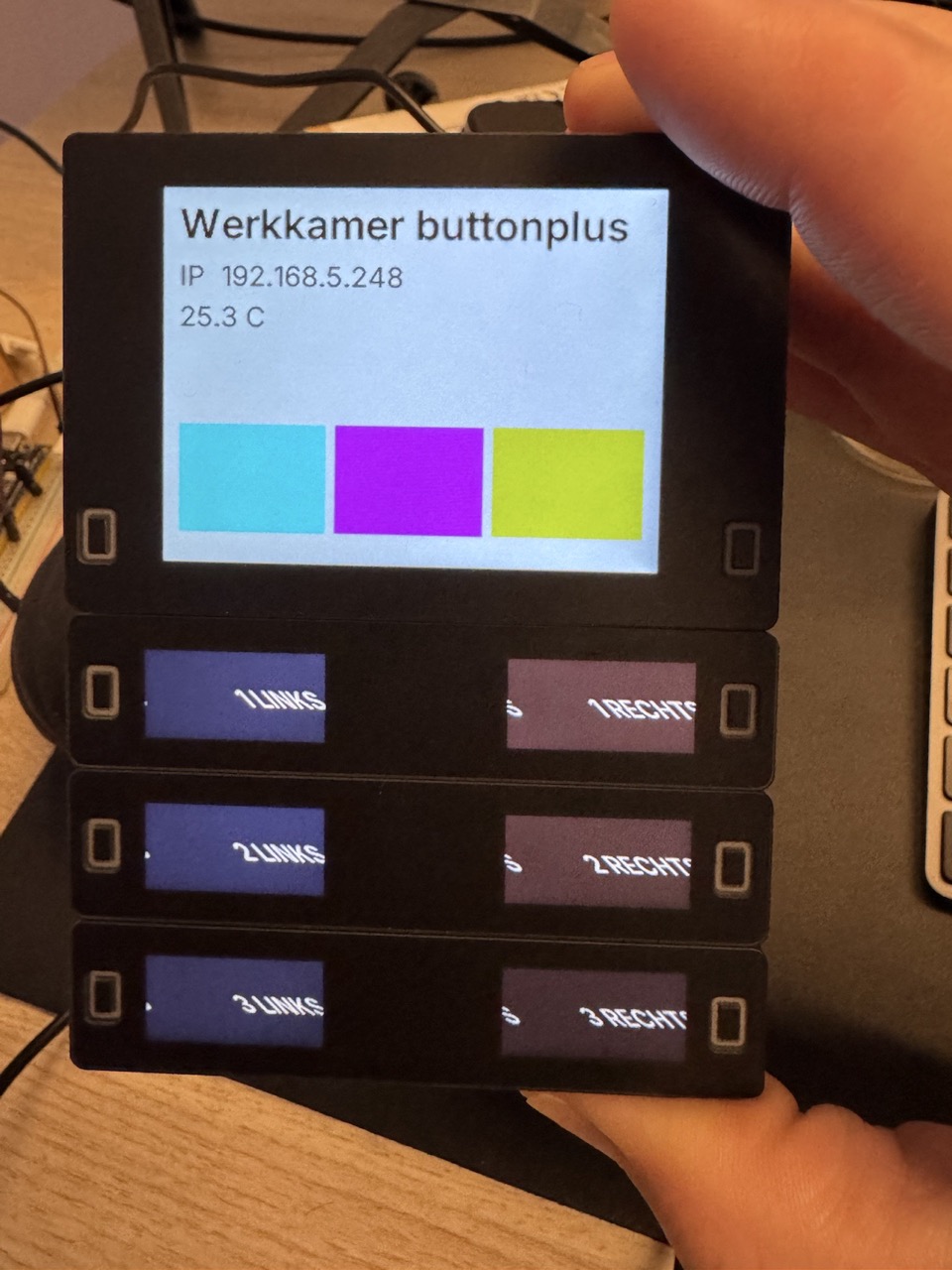
It worked! Yes there are things wrong, but this is a very promising starting point already! For example, none of the test colours are what they should be. But handing the AI a picture of this, it immediately figured out that it wasn’t about driving the colours differently, but that the entire display was inverted. One config line fixed that. The bar panels are also clearly off: the text is clipped and shifted.
The geometry of the bar panels is my favourite example. The datasheet implies a 132x162 pixel memory, but rendering at 162 produced a diagonal smear, because every row wrapped two pixels later than the data supplied. Rather than guess, it put a different candidate geometry on each of the six panels at once and drew a border frame around each:
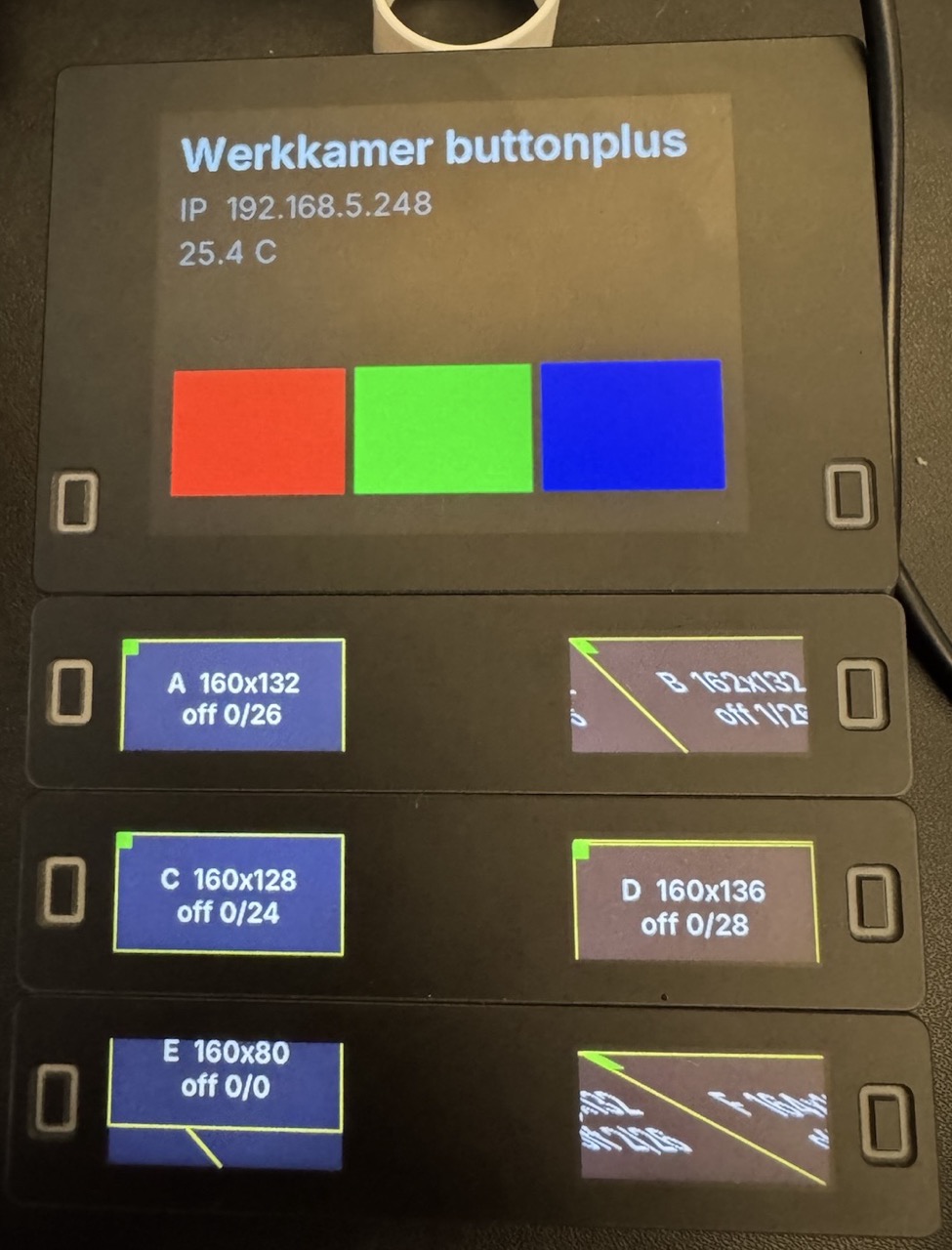
You can read the answer straight off the photo. It needed a bit more tuning later, but it is so awesome to see an AI do this trial-and-error process and just ending up with a working calibration without much effort on my part.
Making it feel fast
Remember the missing button interrupts? Because the expanders are polled from the main loop, anything that blocks the loop is a dropped press. Not blocking the main loop turned into a series of interesting challenges, and it was the most enjoyable engineering in the whole project.
A few things that came out of it:
- Buttons fire on release, not on timeout. The obvious way to tell a click from a hold is to wait out the hold threshold and see what happened. That costs you half a second of latency on every single press. Instead the click fires on the release edge itself and simply looks at how long the press was. The difference in feel is enormous.
- The SPI bus has six device slots and the panel has seven displays. ESP-IDF lets a device register per transaction instead of holding a slot permanently, at a cost of about 8ms per refresh. The most efficient way is to let five displays occupy five slots, plus one slot the remainder of the screens take turns in. Working out which display should pay that cost was worth doing properly: the main screen redraws constantly for the clock and the music progress bar, while a bar panel only redraws when you change page. Giving the main display a permanent slot took its full redraw from 80ms to 64ms.
- All six bar panels refresh in one burst. They share one SPI bus and are selected one at a time, so they can never truly change simultaneously. But pushing all six out back-to-back, instead of letting each wait for its own refresh timer, took a page change from 172ms to about 113ms.
- Album art is resized off-device. Home Assistant serves cover art at 640x640. ESPHome’s JPEG decoder draws one pixel per callback, so that is 409,600 callbacks and about 2.3 seconds with the main loop stopped, during which every button press is lost. Running it through a tiny image resizer on the LAN first brings it to 88x88, which is 43ms. Pressing play now updates the cover art near-instantly.
Page navigation also happens entirely on the device. Pressing a button changes the panel immediately whether or not Home Assistant is reachable. What gets sent to Home Assistant is what the press meant, so scene_avond or media_volume_up rather than which button was pressed. This requires an update on the device when rearranging a page, but it makes for a far simpler setup in Home Assistant.
Making it reusable
I keep my ESPHome configs split in two: a file per device holding whatever makes that device that device, and a common/ tree with the reusable parts every device pulls in.
So woonkamer-buttonplus.yaml holds the things that make this panel the living room one. Which scenes sit on which button, that the music comes from the living room speakers, the layout of the clock and the album art, the Dutch labels. And common/devices/button_plus/ holds everything that is true of any Button+: the hardware definition, the seven displays with their calibration, the buttons, the LEDs, and the page engine that does the navigating.
That helped to open-sourcing the reusable part. It was mostly a move rather than a rewrite. The generic half became mkarnebeek/esphome-button-plus, and my own panel now consumes it straight from GitHub as a pinned ESPHome package.
The reusable part was extended with documentation and examples. It contains one demo you can flash over USB with no Home Assistant, no wifi and no secrets at all. It lights the LEDs and pages around, so you can check your hardware works before deciding what to build on it. The other is my own living room config, published purely as reference, showing how the album art and the progress bar are actually done.
All of this again was done with AI, with me writing the introduction.
Where it ended up
Here is the demo config running, which needs no Home Assistant at all:
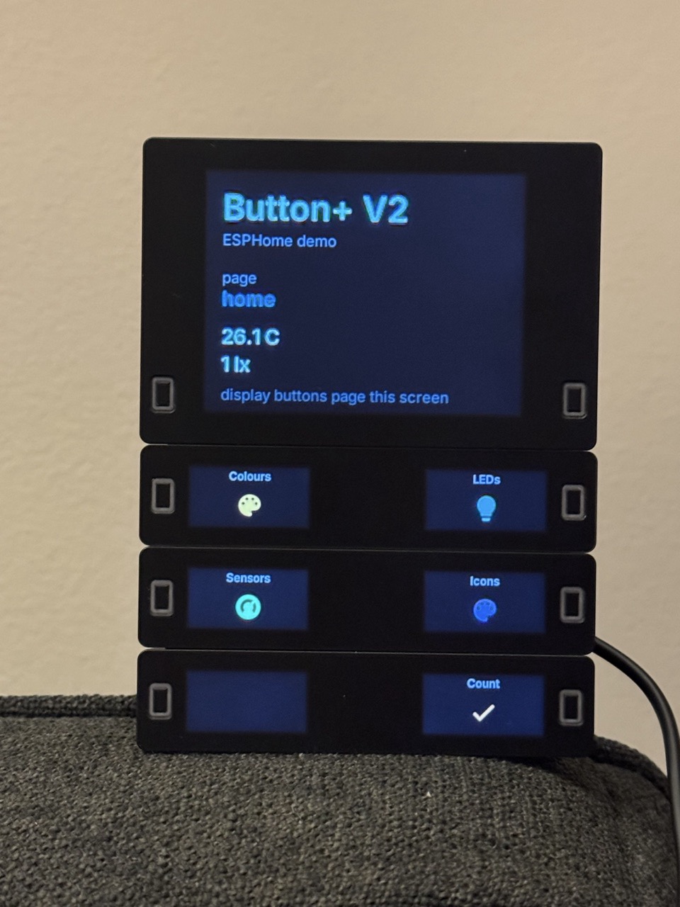
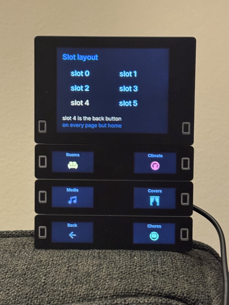
The right-hand photo is the slot layout screen, which maps each physical button to its slot number. Note the bottom-left button showing “Back”: on every page except the home page, the page engine fills that slot with a back button automatically, so pages never have to declare it.
The photo at the top of this post is the living room config: a clock, the album art of whatever is playing and a progress bar, none of which the vendor firmware can draw.
The last thing I need to do is actually put it on a wall somewhere in my home and put it to use. Some ideas:
- The living room of course
- The bathroom, calling up music, scenes or showing the status of the heat pump water tank.
- Kitchen?
- Somewhere else?
Closing
The hardware is awesome. It’s great fun to play with because it looks so nice, and especially because it has the potential of being a valuable addition to the house. The firmware it ships with could be better, but getting ESPHome to run on it turned out to be a fun project on it’s own.
Playing with home automation projects is always great fun: they have this really nice tangible effect in the physical world. Combining this with AI has led to multiple positively surprising moments. Giving it a way to check its own work, by flashing the device and by handing it photos, changed it from something that writes config to something that actually figures things out. The reward you get versus the effort it takes is really motivating.
I hope you had as much fun reading this, as I had on the project. On to the next!
Leave a comment