Building an ESPHome Modbus Thermostat
Changelog
- October 2025: Replaced external component with esp32_ble_server
Introduction
In a previous article I looked at ways to control my heat pump locally. This resulted in a Modbus RTU interface through which I can control the desired functions of the heat pump. In this article I describe how my self-built thermostat makes use of this, what I’m trying to achieve with it and how it works.
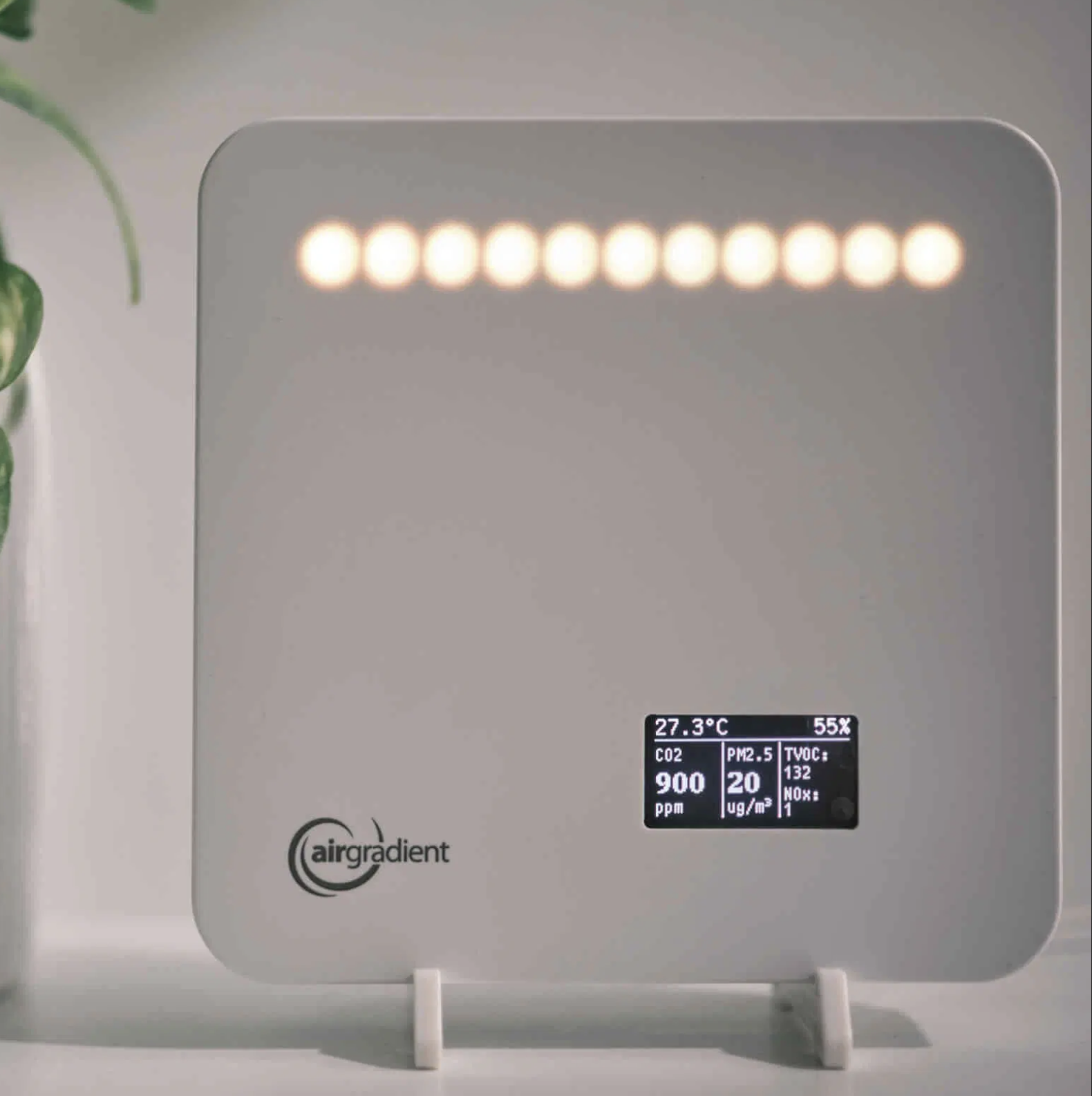
By now, there’s an AirGradient air quality monitor on the living room wall functioning as a thermostat, instead of the Madoka thermostat that came with the heat pump.
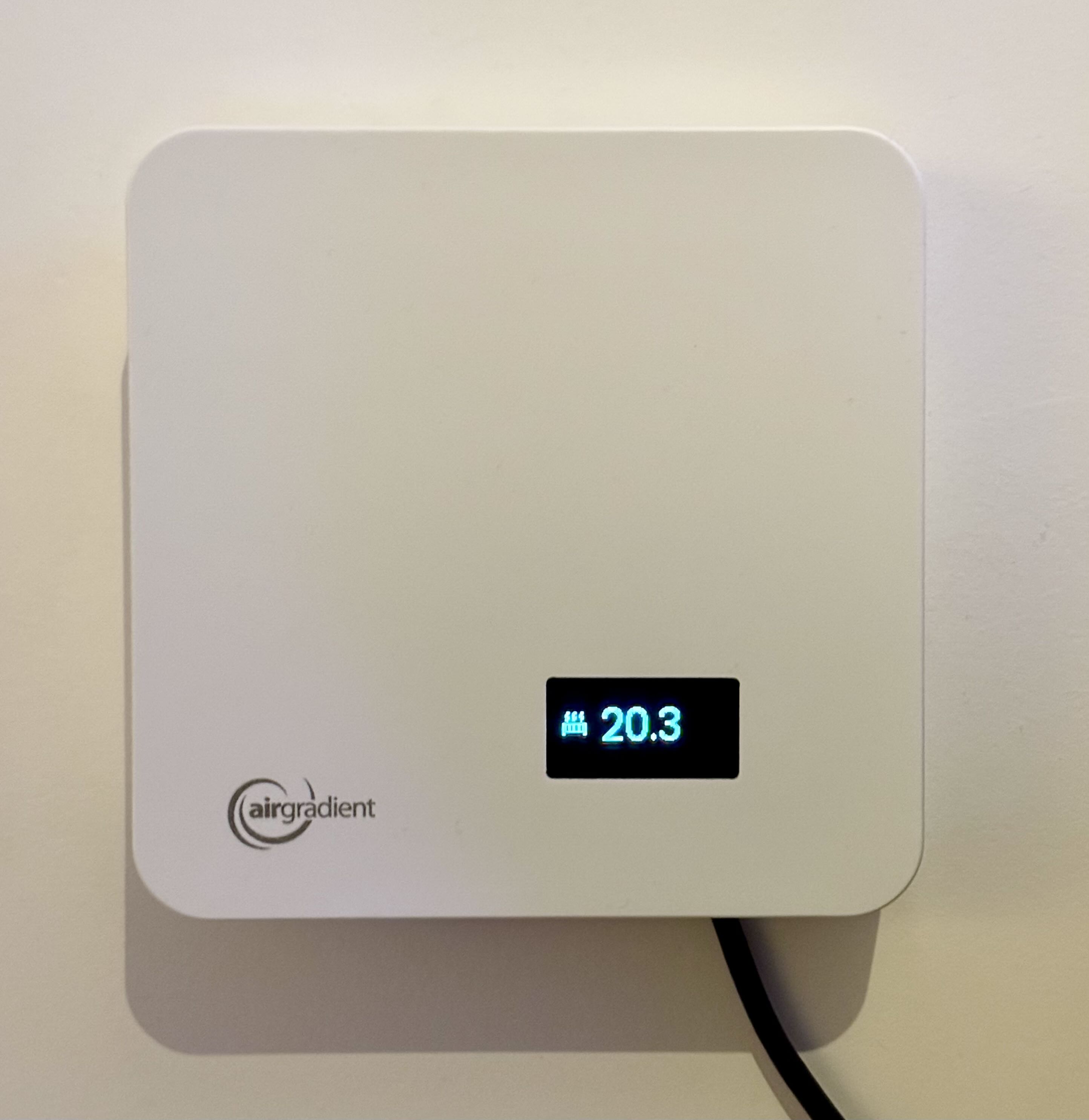
Yes, I still need to properly hide the power cable, but it’s a nice device on the wall. Besides temperature, it can of course also measure air quality and has LEDs and a display for useful information, not just for air quality, but other notifications from Home Assistant can also be displayed here as notifications.
Goal
It’s super cool and educational to build something yourself, but having a list of reasons why you’re doing this is very helpful to stay on track :P. After using the heat pump for over a year, I encountered the following problems that I’d like to solve.
-
Temperature measurement interference: The Daikin thermostat has a deviation of 0.3-0.4 degrees upward when it activates. This is because the LEDs that light up when activating get warm
 . This disturbs the thermostat’s measurement. I expect better from a thermostat
 - Absent modulation: The thermostat’s modulation doesn’t work well. Although it correctly adjusts the leaving water temperature based on the current living room temperature, it will allow the living room temperature to rise up to 1.5 degrees above the setpoint before turning off. This cannot be adjusted. After contacting Daikin, they admit this doesn’t work well, and advise to disable modulation. This effectively makes it an on/off thermostat, which in turn causes a very fluctuating temperature in the living room.
- Fluctuating living room temperature: The thermostat has a hysteresis of 0.5 degrees above and below the set temperature. Combine this with a correctly adjusted heating curve that’s meant to let the heat pump run as smoothly as possible and thus maintain a temperature instead of having the temperature rise, and you get a fluctuation of roughly 1.5 degrees in the living room over several days.
- Limited program: The thermostat can be manually adjusted in steps of 0.5 degrees. The schedule can only be set per whole degree.
-
More efficient use of the backup heater: When it’s warmer than 25 degrees outside, the heat pump can produce water up to 45 degrees maximum with the outdoor unit. Warmer water beyond that will always be produced using the backup heater. This is 2-3x less efficient than the outdoor unit and you would want to avoid it as much as possible.
- The weekly disinfection run (where the tank is heated to 60 degrees) will thus largely run on the backup heater in summer. In summer you’d rather do this in the early morning, and in winter at the warmest part of the day. Having to adjust this setting each season is annoying.
- Setting the tank continuously to 45 degrees is insufficient for us on colder days. For this the heat pump has a heating curve for the tank, so it maintains a higher temperature on colder days. This works okay, except that the low outdoor temperature is maximum 10 degrees. This is too low for my use case (2 large shower heads and a large bath), and I’d like to keep it higher.
Additionally, I’m missing the following features:
- Weather dependent / sun control: When the sun shines a lot, the heating doesn’t need to work as hard. Modulate it back then.
- Fireplace mode: Normally when you light the fireplace, the thermostat will turn off the heating because it’s warm enough in the living room. However, because we don’t have zone control this means the rooms upstairs are also no longer heated, and thus cool down when we use the fireplace. I’d like to ignore the living room temperature and let it continue running on its heating curve (based on the outdoor temperature).
- More efficient disinfection run: We regularly set the tank to 60 degrees ourselves to be able to shower long and take extensive baths. This is effectively a disinfection run if it stayed 60 degrees long enough, so I’d like to count it as such, so it doesn’t unnecessarily decide to heat the tank to 60 degrees a day later for example.
Requirements
- A standalone system, independent of Home Assistant or the computer network functioning. Optimizations can depend on information from Home Assistant or the internet, but the basic functionality for heating the house must function robustly and independently.
- Preferably as little self-built hardware as possible, using existing hardware and open source software as much as possible.
- Possibilities to implement custom logic or adjust existing logic to my wishes. This is a hobby project after all :P.
- Everything powered by mains power. No replacing batteries every year.
Implementation
Modbus RTU control with an ESP32 microcontroller
Modbus RTU is a simple 2-wire interface (only the A+/B- connections are needed. GND is optional) that works directly between these 2 devices. By using a simple physical connection and a microcontroller, instead of creating a dependency on the computer network or Home Assistant, this can function independently.
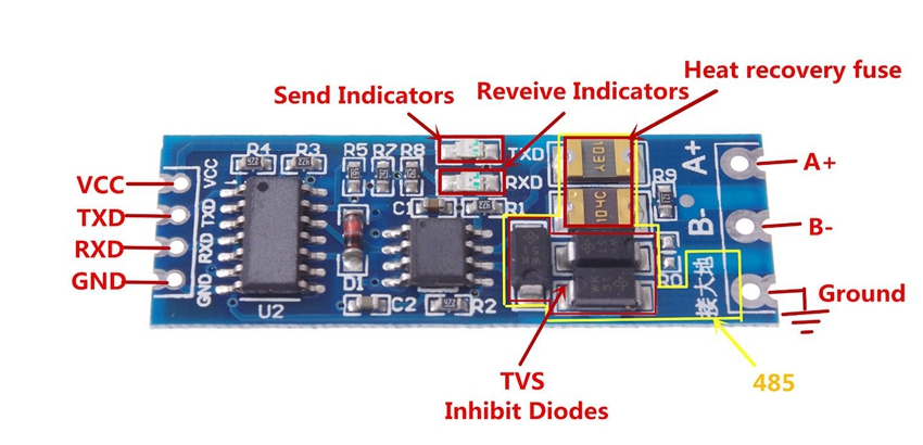
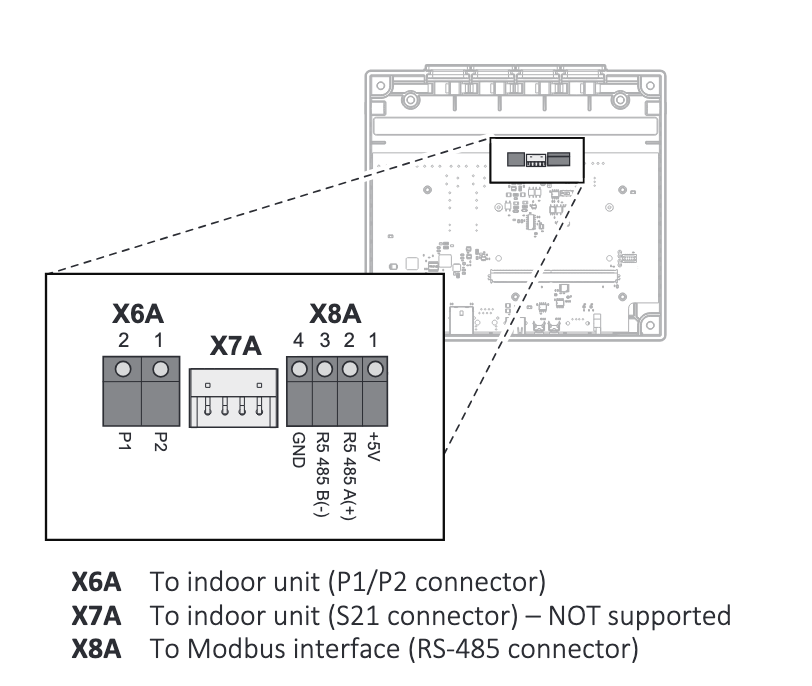
The Daikin Home Hub (2nd image) has, besides power and a P1P2 connection (see X6A in the image), also an RS485 interface (see X8A). This is for Modbus RTU. This is easy to control with an ESP32 microcontroller with a UART-to-RS485 transceiver (1st image).
In the image below you see an enclosure containing an ESP32 microcontroller, an RS485 transceiver (MAX485 IC) and a display. Jurjen had already built this for another project, and had another one laying around, which I can use without any modifications. Neat! Thanks Jurjen! The combination of ESP32 and RS485 transceiver is very common, making it easy to replace in the future should it break down.
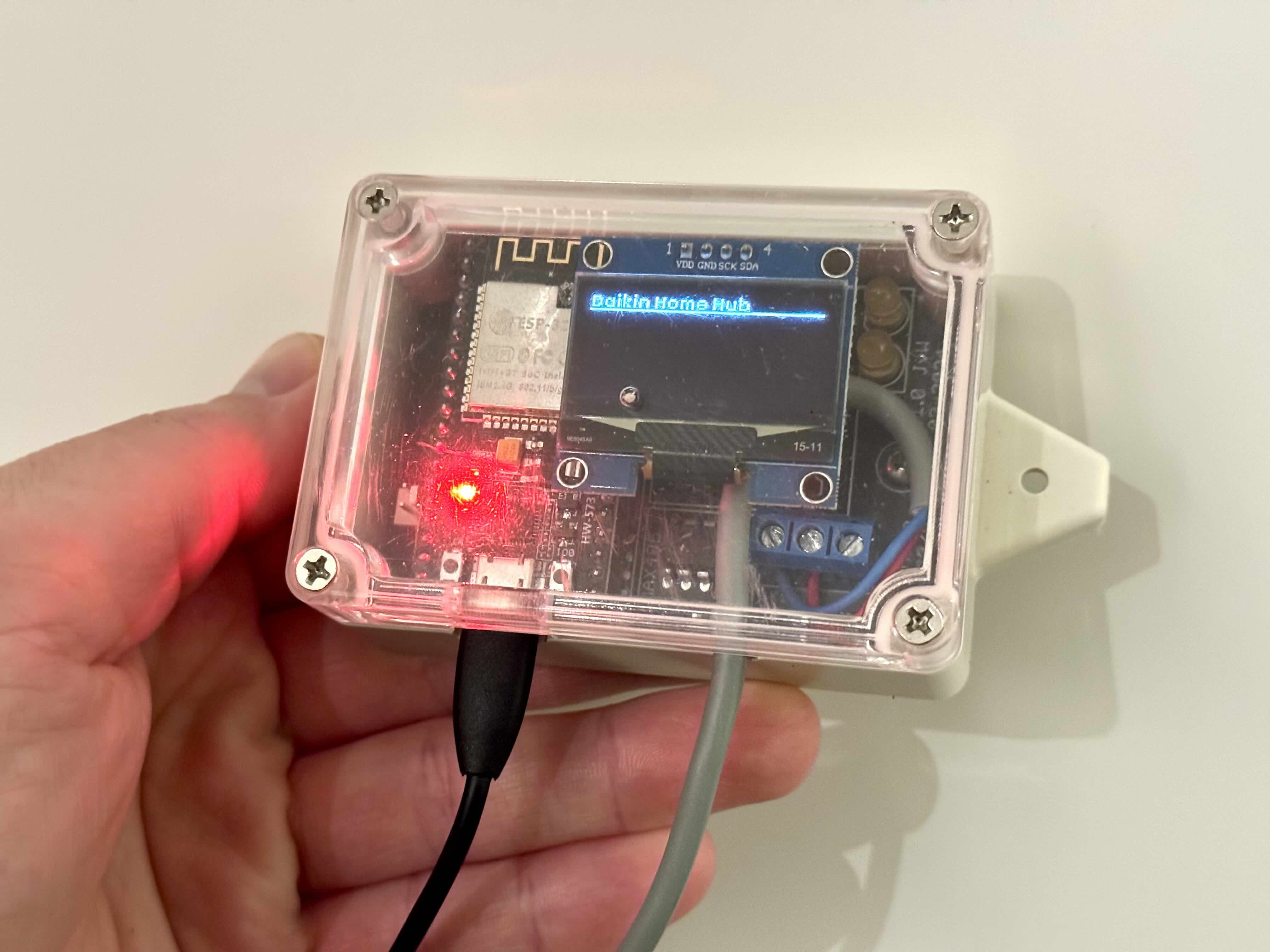
The gray cable is the RS485 connection to the Daikin Home Hub, and the black USB cable is only for power. I placed this microcontroller together with the Daikin Home Hub in the meter cabinet.
Measuring the living room temperature
I already had an AirGradient air quality meter in the living room, which I had already flashed with ESPHome and it has a display that can show some useful information. I’d like to reuse this as a thermostat instead of having another device in the living room. This can easily hang on the wall where the thermostat is now. Supplemented with some icons for heat demand and whether the hot water tank is being filled.
Thermostat logic
In theory I could combine these 2 devices, but since I prefer to use as little modifications or self-built hardware as possible, it’s more convenient to connect them to each other. Since they both use an ESP32 and these have Bluetooth, this is very easy to do wirelessly with Bluetooth Low Energy! The thermostat wires in the wall are then only needed for power.
Now the question is, in which of the two ESP32s do we run the thermostat logic? Traditionally this runs in the device on the wall in the living room. But, this being wireless and I want some failure resilience, I choose to run it in the meter cabinet. This means the AirGradient in the living room only needs to behave as a generic bluetooth temperature sensor. This keeps the responsibilities of the devices nicely separated, communication standarized, and easily replaceable or expandable in the future, for example for zone control.
If the bluetooth connection with the AirGradient fails, the heating will still be able to function in a limited way, based only on the outdoor temperature measured by the outdoor unit.
Component overview
By now there are quite a few components, but the basis is still relatively simple.
If we also include the optional communication and ESPAltherma for example (as dotted lines), we get the following diagram.
ESPHome
For the firmware on the ESP32 I used ESPHome, because it already has support for modbus and thermostat logic on board and the further (optional) communication with Home Assistant is then very easy.
Note that if ESPHome loses connection with Home Assistant or wifi, it will by default restart periodically. It’s not recommended to disable this, but you can set this to a higher value. See the ESPHome documentation: ESPHome intentionally reboots in specific situations about this.
Living room temperature via BLE
Since ESPHome 2025.2 it has native support for acting as a BLE server. Confguring this, I now have an AirGradient that also acts as a BLE sensor.
Previously, I used an external component from wifwucite for this, because ESPHome couldn’t do that yet.
esp32_ble_server:
  services:
    - uuid: 8a8e4590-3b3f-4343-acea-d59fc70e04fd
      advertise: false
      characteristics:
        - id: temp_characteristic
          uuid: ae879a07-2182-4ec1-926e-b4a214769421
          read: true
          notify: true
          description: Temperature
          value:
            # There is probably a simpler way to do this magic,
            # but this works for me.
            data: !lambda |-
              float value = id(temp).state;
              return bytebuffer::ByteBuffer::wrap(value).get_data();
        - id: humidity_characteristic
          uuid: ae879a07-2182-4ec1-926e-b4a214769422
          read: true
          notify: true
          description: Humidity
          value:
            data: !lambda |-
              float value = id(humidity).state;
              return bytebuffer::ByteBuffer::wrap(value).get_data();
Once you boot the AirGradient with this configuration, check the logs for the mac address. You’ll need this later. Note that this is a different mac address than the wifi one, and often only differs in the last letter/digit.
...
[23:24:34][C][esp32_ble_controller:318]: Bluetooth Low Energy Controller:
[23:24:34][C][esp32_ble_controller:319]:   BLE device address: 84:fc:e6:02:5a:ce
...
On the other ESP side, the following configuration is sufficient to make this available as a sensor.
esp32_ble_tracker: # required component

ble_client:
  # The BLE mac address of the AirGradient
  - mac_address: AB:CD:EF:12:34:56
    id: airgradient_living_room

sensor:
  # Temperature. Do the same for humidity.
  - id: airgradient_living_room_temperature_ble
    platform: ble_client
    type: characteristic
    ble_client_id: airgradient_living_room
    name: "AirGradient Living Room Temperature BLE"
    service_uuid: "8a8e4590-3b3f-4343-acea-d59fc70e04fd"
    characteristic_uuid: "ae879a07-2182-4ec1-926e-b4a214769421"
    icon: "mdi:thermometer"
    unit_of_measurement: "°C"
    notify: true
    accuracy_decimals: 2
    # Nothing to see here,
    # just some magic to convert the bytes to a float
    lambda: |-
      return *((float*)(&x[0]));
The BLE connection is an active one. This has the advantage that the ESP32 knows when it drops out. This is useful for monitoring, but it also means we can determine how our thermostat logic handles this. For now, I have configured ESPHome to use the last known value. This works fine for brief signal dropouts. This can be extended with, for example, falling back to the heating curve when it drops out for a longer period of time.
  - platform: template
    id: airgradient_living_room_temperature
    name: "AirGradient Living Room Temperature"
    # translate unavailable to 0
    lambda: |-
      if (id(airgradient_living_room_temperature_ble).state > 5 && id(airgradient_living_room_temperature_ble).state < 50) {
        return id(airgradient_living_room_temperature_ble).state;
      } else {
        return 0;
      }
    update_interval: 5s
    accuracy_decimals: 2
    icon: "mdi:thermometer"
    unit_of_measurement: "°C"
    filters:
      # ignore unavailable (0) value
      - clamp:
          min_value: 5
          max_value: 50
          ignore_out_of_range: true
Modbus connection
On Daikin’s website for the Home Hub, at the bottom of the page, you can find the “Installation manual for installers”. This document contains several parameters for the Modbus RTU interface of the Daikin Home Hub.
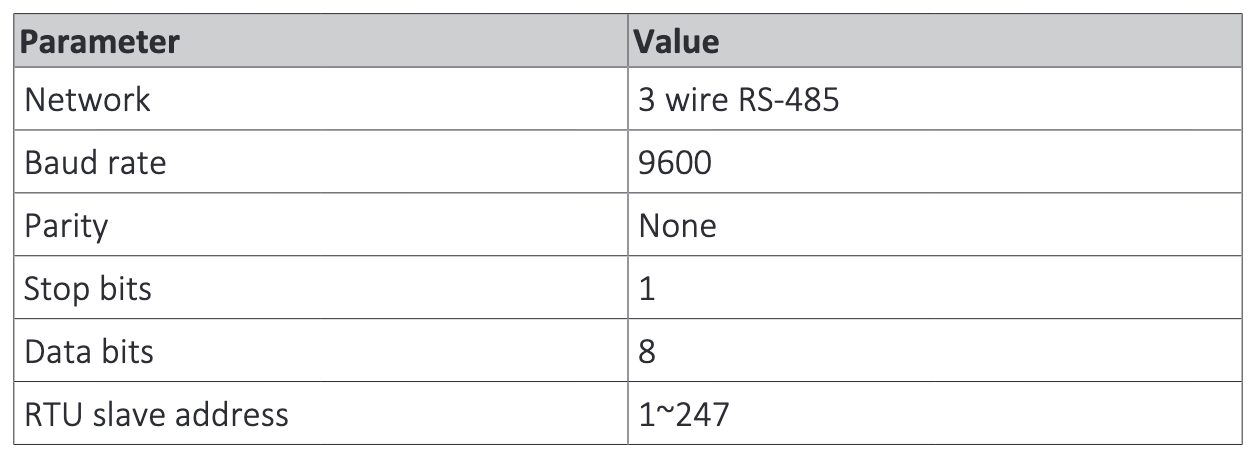
Then, based on the ESPHome documentation for the Modbus Controller, I used the following YAML configuration. Note that the GPIO pins, baud rate and the need for a flow control pin are specific to the MAX485 IC. Check how your specific IC and/or transceiver is connected and configure these correctly.
uart:
  id: mod_bus
  tx_pin: GPIO17
  rx_pin: GPIO16
  baud_rate: 9600

modbus:
  id: modbus1
  uart_id: mod_bus
  flow_control_pin: GPIO18

modbus_controller:
  - id: daikin_ekrhh
    # This address is configured when connecting
    # the Home Hub to the heat pump, but defaults to 1.
    address: 0x1
    modbus_id: modbus1
    setup_priority: -10
    update_interval: 20s
Reading and writing registers
Now that we have a connection with the Daikin Home Hub, we can read and write registers. Modbus has several register types, but the Daikin Home Hub only uses 2:
- Holding Registers: These can be read and written.
- Input Registers: These can only be read.
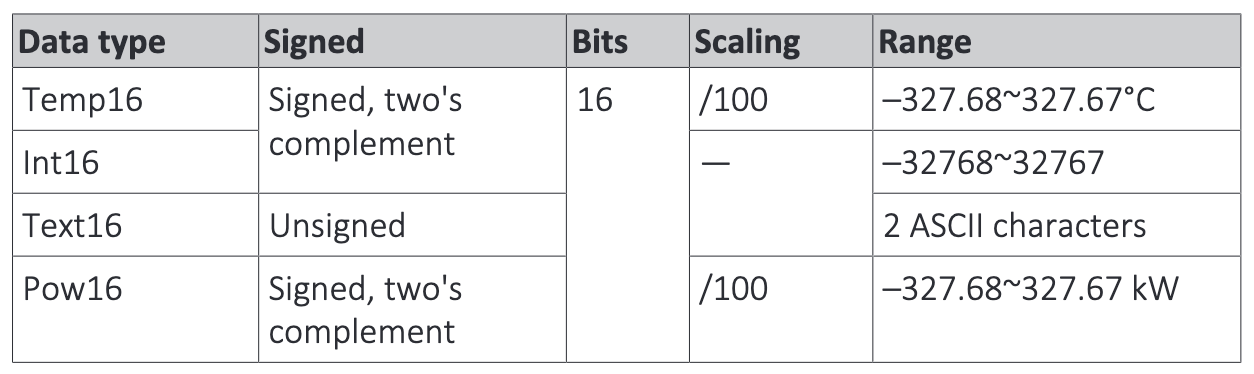
The manual also defines some formats for values in these registers.
The manual then publishes a list of values that we can read and write.
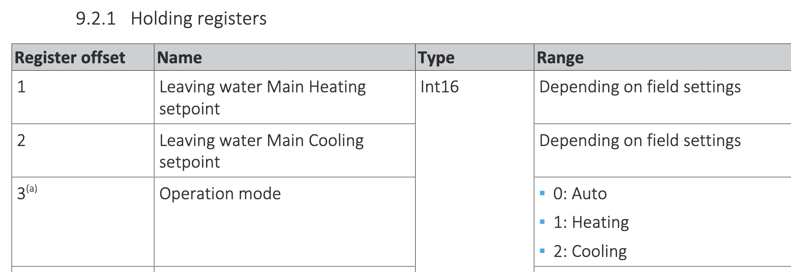
Which can be used in ESPHome as follows:
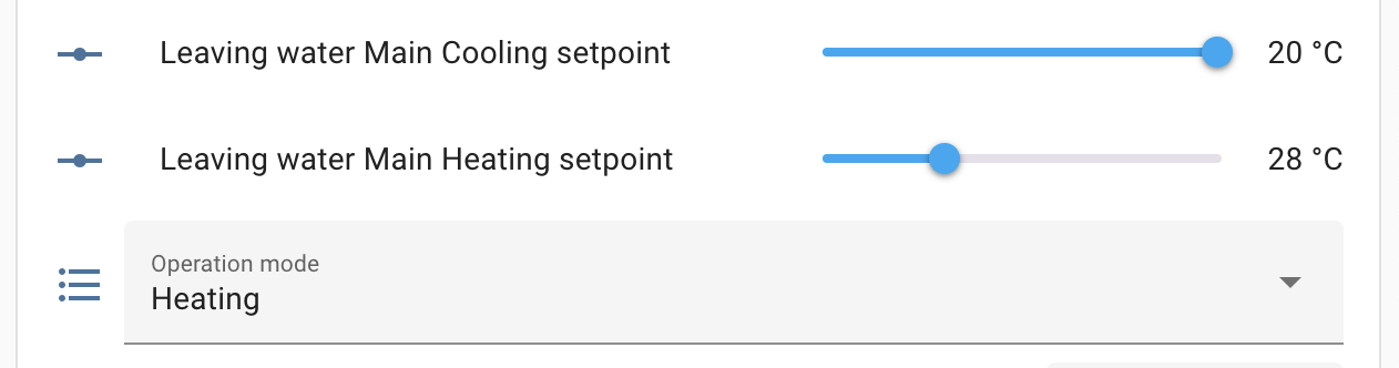
number:
  - platform: modbus_controller
    modbus_controller_id: daikin_ekrhh
    name: "Leaving water Main Heating setpoint"
    register_type: holding
    address: 0
    unit_of_measurement: "°C"
    value_type: S_WORD # This is a 16-bit integer
    min_value: 25 # these are your min and max heating curve values
    max_value: 35
    lambda: |-
      if (x > 100 || x < 0) { return NAN;}
      return x;

  - platform: modbus_controller
    modbus_controller_id: daikin_ekrhh
    name: "Leaving water Main Cooling setpoint"
    register_type: holding
    address: 1
    unit_of_measurement: "°C"
    value_type: S_WORD
    min_value: 17
    max_value: 20
    lambda: |-
      if (x > 100 || x < 0) { return NAN;}
      return x;

select:
  - platform: modbus_controller
    id: operation_mode_select
    name: "Operation mode"
    address: 2
    value_type: S_WORD
    optionsmap:
      "Auto": 0
      "Heating": 1
      "Cooling": 2
The lambda blocks filter out all values outside a valid range (0-100). This is meant to filter out values where all bits are set to 1, and esphome interperts that as 32767. The Daikin Home Hub does this when the value is unavailable for whatever reason. For example when the heat pump is rebooting.
Once the ESPHome firmware is built and added to Home Assistant, it appears in Home Assistant as follows:
Useful registers
Ok, passing absolute values for supply temperature is nice, but actually I want the heat pump to do the things it’s good at. I’ll just be adding logic to it. So registers for manipulating the heating curve instead of explicitly setting a value it are more interesting. Below is an overview of the registers I use, and for what I use them. Keep in mind that I disconnected the Daikin thermostat and the unit itself only has access to the outdoor temperature measured by the outdoor unit.
- Operation mode: Auto, Heating, Cooling: Auto will automatically switch between cooling and heating. I will explicitly set this to cooling or heating, because the ESPHome climate component also supports this, and this prevents setting up the two in a way this could lead to one cooling, where the other meant heating.
- Space heating/cooling: ON/OFF: This switches room heating on or off. See also “In operation” in the heat pump menu. I use this to inform the heat pump about thermostat demand. I would like to use a different way, but since the heat pump no longer is aware of a thermostat, this is the next best thing. The anti-frost protection mechanism still works when this is turned off, because it now looks at the outside temperature being below 4 degrees.
- DHW setpoint: Absolute desired tank temperature. Only works if the heat pump is in “Fixed” setpoint. Since I want to create my own logic for the disinfection run, and want to distinguish between 2 powerful modes (one up to the max of the outdoor unit: 55 degrees, and the other up to the maximum of the indoor unit: 60 degrees), and a possible heating curve is not difficult to build yourself, I will set this as an absolute value myself.
- DHW reheat ON/OFF: Enables/disables tank heating. See also “In operation” in the heat pump menu. Useful for when on vacation.
- DHW booster mode ON/OFF: This activates the booster mode of the heat pump. This is an extra heating that the heat pump can turn on to get the tank up to temperature faster. I have set the temperature for this on the heat pump to 60 degrees. This becomes the most powerful of the 2 powerful modes.
-
Weather dependent mode - Main LWT Heating setpoint offset: If the heat pump is set to heating curve for space heating (why would you set it to anything else?), then you can use this offset to manipulate the heating curve. Set this to -1 to lower the heating curve by 1 degree. I use this to implement modulation.
- The Daikin thermostat is able to do this more granular than a whole degree, and the only reason why this is so coarse is the definition on the modbus registers now allowing for floats. Daikin, if you’re reading along: Why didn’t you do a /100 scaling (Temp16 datatype as you declare it in the manual) for this like you did for the rest of the values?
- There is also a cooling one, but since the curve set for that is so limited, and in practice the living room is always 2 degrees or so higher than the cooling setpoint, that modulation in practice does nothing.
- Smart Grid operation mode, Power limit during Recommended on / buffering and General power limit: These registers are for setting the maximum power of the heat pump. This is useful for optimizing self-consumption of solar panels and buffering energy in the underfloor heating and tank. Just note that you need to set “Smart Grid support” to “Modbus control” in the heat pump, otherwise the heat pump ignores what you specify here.
Thermostat logic
Ok, now for the thermostat logic. ESPHome has a component for this that you can configure to your liking.
In the *_action: you can manipulate the Operation mode: Auto, Heating, Cooling and Space heating/cooling: ON/OFF registers. However, before you do that, set the heat pump to control the supply temperature, instead of the living room thermostat, and disconnect the wiring from the Madoka thermostat.
climate:
  - platform: thermostat
    id: living_room_thermostat
    on_boot_restore_from: memory
    name: Living Room Thermostat
    icon: mdi:heat-pump

    visual:
      min_temperature: 18
      max_temperature: 25
      temperature_step: 0.1

    # Sensors
    sensor: airgradient_living_room_temperature
    humidity_sensor: airgradient_living_room_humidity

    # Presets
    default_preset: Normal
    preset:
      - name: Normal
        default_target_temperature_low: 20.2
        default_target_temperature_high: 23.5
        mode: heat_cool
      - name: Vacation
        default_target_temperature_low: 19.0
        default_target_temperature_high: 23.5
        mode: heat

    # Some safeguards
    min_cooling_off_time: 60s
    min_cooling_run_time: 60s
    min_heating_off_time: 60s
    min_heating_run_time: 60s
    min_idle_time: 60s
    startup_delay: true
    set_point_minimum_differential: 1

    # Deadbands
    cool_deadband: 0.5
    cool_overrun: 0.0
    heat_overrun: 0.5
    heat_deadband: 0.2

    # Actions
    cool_action:
      ...
    heat_action:
      ...
    idle_action:
      ...
Then it looks beautiful in Home Assistant:
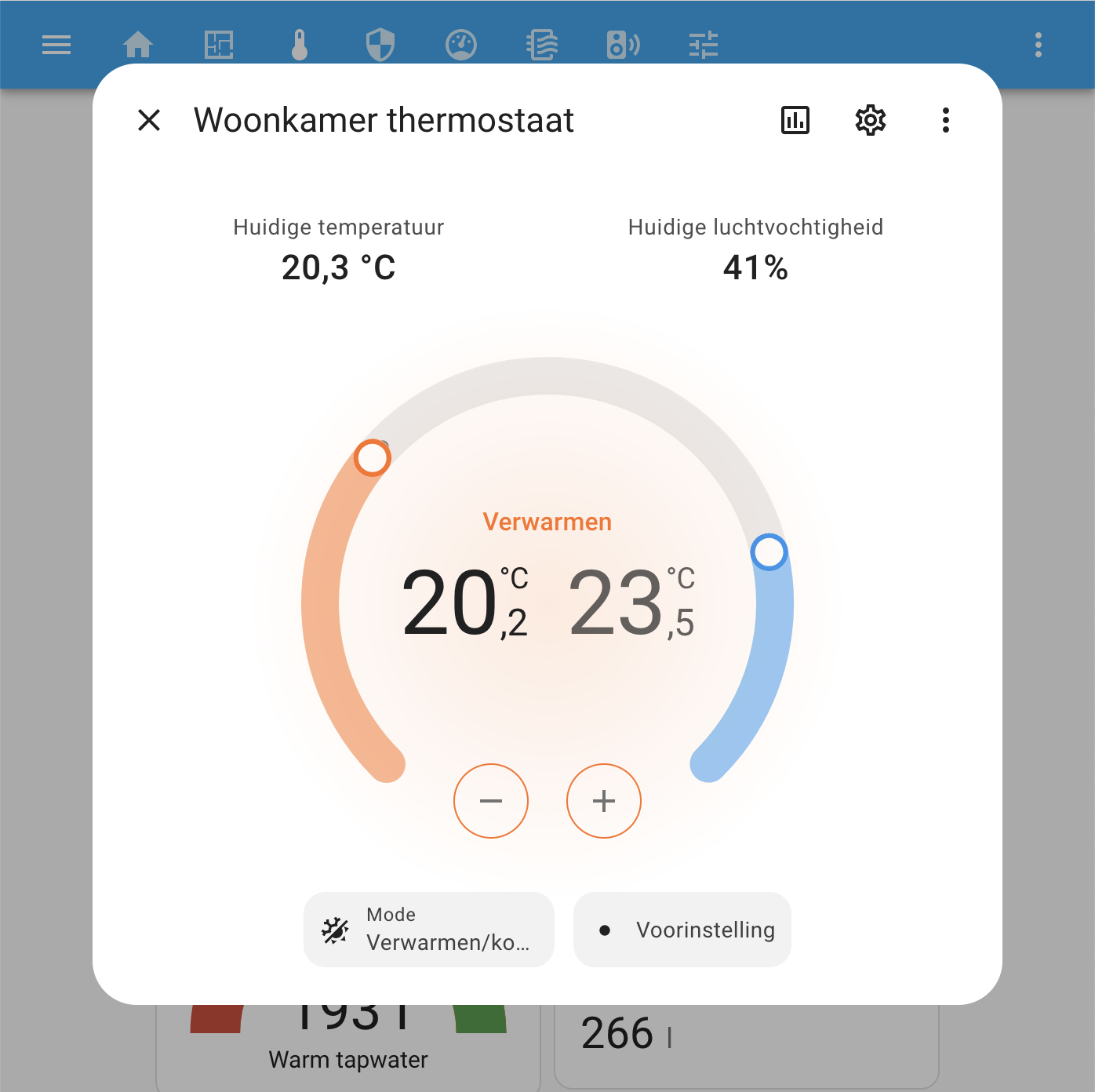
Tweaking and features
This component has one caveat… If the living room temperature is within the deadband/overrun, and the microcontroller reboots, the thermostat will jump to “idle”, even if it was previously “heating”. The consequence is that the heat pump turns off during a microcontroller reboot until it reaches the bottom of the deadband again. Since we know the current status of the heat pump by reading a modbus register, we can work around this. However, the workaround is quite ugly… namely, temporarily increasing the thermostat setpoint to activate it, then setting it back again. ![]()
Besides reactivating the thermostat after a reboot and adding heating curve modulation, there are other tweaks. Like not waiting until you reach the deadband, but turning on the heat pump earlier when you know it’s cold outside. This prevents the long startup and warm-up time of the heat pump from causing the living room temperature to drop further below the setpoint, allowing you to “land” it nicely on the setpoint. Or optimizing tank disinfection: if I’ve set it to 60 myself, don’t do it again the next day just because the planning says so.
Additionally, there are features I want to add, such as automatic fireplace mode, and incorporating living room solar radiation and the number of people in the living room in determining effective modulation. All this to further stabilize the living room temperature.
More about this in a future post.
Leave a comment